An antenna (plural antennae or antennas), or aerial, is an electrical device which converts electric power into radio waves, and vice versa.[1] It is usually used with a radio transmitter or radio receiver. In transmission, a radio transmitter supplies an electric current oscillating at radio frequency (i.e. a high frequency alternating current (AC)) to the antenna's terminals, and the antenna radiates the energy from the current as electromagnetic waves (radio waves). In reception, an antenna intercepts some of the power of an electromagnetic wave in order to produce a tiny voltage at its terminals, that is applied to a receiver to be amplified.
Antennas are essential components of all equipment that uses radio. They are used in systems such as radio broadcasting,broadcast television, two-way radio, communications receivers, radar, cell phones, and satellite communications, as well as other devices such as garage door openers, wireless microphones, Bluetooth-enabled devices, wireless computer networks, baby monitors, and RFID tags on merchandise.
Typically an antenna consists of an arrangement of metallic conductors (elements), electrically connected (often through atransmission line) to the receiver or transmitter. An oscillating current of electrons forced through the antenna by a transmitter will create an oscillating magnetic field around the antenna elements, while the charge of the electrons also creates an oscillating electric field along the elements. These time-varying fields radiate away from the antenna into space as a moving transverse electromagnetic field wave. Conversely, during reception, the oscillating electric and magnetic fields of an incoming radio wave exert force on the electrons in the antenna elements, causing them to move back and forth, creating oscillating currents in the antenna.
Antennas can be designed to transmit and receive radio waves in all horizontal directions equally (omnidirectional antennas), or preferentially in a particular direction (directional or high gain antennas). In the latter case, an antenna may also include additional elements or surfaces with no electrical connection to the transmitter or receiver, such as parasitic elements, parabolic reflectors or horns, which serve to direct the radio waves into a beam or other desired radiation pattern.
The first antennas were built in 1888 by German physicist Heinrich Hertz in his pioneering experiments to prove the existence of electromagnetic waves predicted by the theory ofJames Clerk Maxwell. Hertz placed dipole antennas at the focal point of parabolic reflectors for both transmitting and receiving. He published his work in Annalen der Physik und Chemie
Antenna types[edit]
Antennas can be classified in various ways. The list below groups together antennas under common operating principles, following the way antennas are classified in many engineering textbooks.[17][18][19]
Isotropic: An isotropic antenna (isotropic radiator) is a hypothetical antenna that radiates equal signal power in all directions. It is a mathematical model that is used as the base of comparison to calculate the gain of real antennas. No real antenna can have an isotropic radiation pattern. However approximately isotropic antennas, constructed with multiple elements, are used in antenna testing.
The first four groups below are resonant antennas; when driven at their resonant frequency their elements act as resonators. Waves of voltage and current bounce back and forth between the ends, creating standing waves in the metal elements, increasing output power
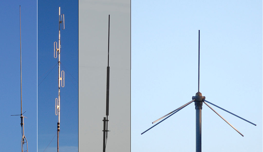
Monopole[edit]


Monopole antennas consist of a single radiating element such as a metal rod, often mounted over a conducting surface, a ground plane.[18][20] One side of the feedline from the receiver or transmitter is connected to the rod, and the other side to the ground plane, which may be the Earth. The most common form is the quarter-wave monopole which is one-quarter of a wavelength long and has a gain of 5.12 dBi when mounted over a ground plane. Monopoles have an omnidirectional radiation pattern, so they are used for broad coverage of an area, and have vertical polarization. The ground waves used for broadcasting at low frequencies must be vertically polarized, so large vertical monopole antennas are used for broadcasting in the MF, LF, and VLF bands. Small monopoles are used as nondirectional antennas on portable radios in the HF, VHF, and UHF bands.
- Whip - Type of antenna used on mobile and portable radios in the VHF and UHF bands such as boom boxes, consists of a flexible rod, often made of telescoping segments.
- Rubber Ducky - Most common antenna used on portable two way radios and cordless phones due to its compactness, consists of an electrically short wire helix. The helix adds inductance to cancel the capacitive reactance of the short radiator, making it resonant. Very low gain.
- Ground plane - a whip antenna with several rods extending horizontally from base of whip attached to the ground side of the feedline. Since whips are mounted above ground, the horizontal rods form an artificial ground plane under the antenna to increase its gain. Used as base station antennas for land mobile radio systems such as police, ambulance and taxi dispatchers.
- Mast radiator - A radio tower in which the tower structure itself serves as the antenna. Common form of transmitting antenna for AM radio stations and other MF and LF transmitters. At its base the tower is mounted on a ceramic insulator to isolate it from the ground.
- T and inverted L - Consist of a long horizontal wire suspended between two towers with insulators, with a vertical wire hanging down from it, attached to a feedline to the receiver or transmitter. Used on LF and VLF bands. The vertical wire serves as the radiator. Since at these frequencies the vertical wire is electrically short, much shorter than a quarter wavelength, the horizontal wire(s) serve as a capacitive "hat" to increase the current in the vertical radiator, increasing the gain. Very narrow bandwidth, requiresloading coil to tune out the capacitive reactance and make it resonant. Requires low resistance ground (electricity)
- Inverted F - Combines the advantages of the inverted-L antenna and the F-type antenna of, respectively, compactness and good matching. The antenna is grounded at the base and fed at some intermediate point. The position of the feed point determines the antenna impedance. Thus, matching can be achieved without the need for an extraneous matching network.
- Umbrella - Very large wire transmitting antennas used on VLF bands. Consists of a central mast radiator tower attached at the top to multiple wires extending out radially from the mast to ground, like a tent or umbrella, insulated at the ends. Extremely narrow bandwidth, requires large loading coil and low resistance counterpoise ground. Used for long range military communications.
Dipole[edit]


The most widely-used class of antenna, a dipole antenna consists of two symmetrical radiators such as metal rods or wires, with one side of the balanced feedline from the transmitter or receiver attached to each.[18][21] A horizontal dipole radiates in two lobes perpendicular to the antenna's axis. A half-wave dipole the most common type, has two collinear elements each a quarter wavelength long and a gain of 2.15 dBi. Used individually as low gain antennas, dipoles are also used as driven elements in many more complicated higher gain types of antennas.
- Yagi-Uda - One of the most common directional antennas at HF, VHF, and UHF frequencies. Consists of multiple half wave dipole elements in a line, with a single driven element and multiple parasitic elements which serve to focus the radio waves in a beam. It radiates a unidirectional beam with gain up to about 17 dBi depending on the number of elements used, and has a narrow bandwidth of a few percent. Used for rooftop television antennas, point-to-point communication links, and long distanceshortwave communication using skywave ("skip") reflection from the ionosphere.
- Log periodic - Unique in that it is a high gain dipole antenna with broad bandwidth. It consists of many dipole driven elements in a line, with alternating polarization and gradually increasing width. Used for rooftop television antennas.
- Turnstile - Two dipole antennas mounted at right angles, fed with a phase difference of 90°. This can radiate horizontally polarized radio waves broadside in an omnidirectional pattern, and circularly polarized radio waves off the end. Used for receiving signals from satellites, as circular polarization is used for satellite communication since it is not sensitive to the orientation of the satellite's antenna.
- Corner reflector - A directive antenna with moderate gain of 15 - 20 dBi used at UHF frequencies. Consists of a dipole mounted in front of two reflective metal screens joined at an angle, usually 90°. Used as a rooftop UHF television antenna and for point-to-point data links.
- Patch (microstrip) - A type of antenna with elements consisting of metal sheets mounted over a ground plane. Similar to dipole with gain of 6 - 9 dBi. Integrated into surfaces such as aircraft bodies. Their easy fabrication using PCB techniques have made them popular in modern wireless devices. Often used in arrays.
Array[edit]


Array antennas consist of multiple antennas working as a single antenna. Typically they consist of arrays of identical driven elements, usually dipoles fed in phase, giving increased gain over that of a single dipole.[18][22][23]
- Collinear - Consist of a number of dipoles in a vertical line. It is a high gain omnidirectional antenna, meaning more of the power is radiated in horizontal directions and less into the sky or ground and wasted. Gain of 8 to 10 dBi. Used as base station antennas for land mobile radio systems such as police, fire, ambulance, and taxi dispatchers, and sector antennas for cellular base stations.
- Reflective array - multiple dipoles in a two-dimensional array mounted in front of a flat reflecting screen. Used for radar and UHF television transmitting and receiving antennas.
- Phased array - A high gain antenna used at UHF and microwave frequencies which is electronically steerable. It consists of multiple dipoles in a two-dimensional array, each fed through an electronic phase shifter, with the phase shifters controlled by a computer control system. The beam can be instantly pointed in any direction over a wide angle in front of the antenna. Used for military radar and jamming systems.
- Curtain array - Large directional wire transmitting antenna used at HF by shortwave broadcasting stations. It consists of a vertical rectangular array of wire dipoles suspended in front of a flat reflector screen consisting of a vertical "curtain" of parallel wires, all supported between two metal towers. It radiates a horizontal beam of radio waves into the sky above the horizon, which is reflected by the ionosphere to Earth beyond the horizon
- Batwing or superturnstile - A specialized antenna used in television broadcasting consisting of perpendicular pairs of dipoles with radiators resembling bat wings. Multiple batwing antennas are stacked vertically on a mast to make VHF television broadcast antennas. Omnidirectional radiation pattern with high gain in horizontal directions. The batwing shape gives them wide bandwidth.
- microstrip - an array of patch antennas on a substrate fed by microstrip feedlines. Microwave antenna that can achieve large gains in compact space. Ease of fabrication byPCB techniques have made them popular in modern wireless devices. Beamwidth and polarization can be actively reconfigurable.
Loop[edit]


Loop antennas consist of a loop or coil of wire.[18][24][25] Loops with circumference of a wavelength or larger act similarly to dipole antennas. However loops small in comparison to a wavelength act differently. They interact with the magnetic field of the radio wave instead of the electric field as other antennas do, and so are relatively insensitive to nearby electrical noise. However they have low radiation resistance, and so are inefficient for transmitting. They are used as receiving antennas at low frequencies, and also as direction finding antennas.
- Ferrite (loopstick) - Used as the receiving antenna in virtually all AM radios at MF, LF, and VLF frequencies. A coil of wire wrapped around a ferrite magnetic core. The magnetic core concentrates the magnetic field, enabling this small compact antenna to receive radio waves many times its size. Has two main lobes off the ends of the ferrite stick.
Aperture[edit]


Aperture antennas are the main type of directional antennas used at microwave frequencies and above.[18][26] They consist of a small dipole or loop feed antenna inside a three-dimensional guiding structure large compared to a wavelength, with an aperture to emit the radio waves. Since the antenna structure itself is nonresonant they can be used over a wide frequency range by replacing or tuning the feed antenna.
- Parabolic - The most widely used high gain antenna at microwave frequencies and above. Consists of a dish-shaped metal parabolic reflector with a feed antenna at the focus. It can have some of the highest gains of any antenna type, up to 60 dBi, but the dish must be large compared to a wavelength. Used for radar antennas, point-to-point data links, satellite communication, and radio telescopes
- Horn - Simple antenna with moderate gains of 15 to 25 dBi consists of a flaring metal horn attached to a waveguide. Used for applications such as radar guns, radiometersand as feed antennas for parabolic dishes.
- Slot - Consist of a waveguide with one or more slots cut in it to emit the microwaves. Linear slot antennas emit narrow fan-shaped beams. Used as UHF broadcast antennas and marine radar antennas.
- Dielectric resonator - consists of small ball or puck-shaped piece of dielectric material excited by aperture in waveguide Used at millimeter wave frequencies
Traveling wave[edit]


Unlike the above antennas, traveling wave antennas are nonresonant so they have inherently broad bandwidth.[18][27] They are typically wire antennas multiple wavelengths long, through which the voltage and current waves travel in one direction, instead of bouncing back and forth to form standing waves as in resonant antennas. They have linear polarization (except for the helical antenna). Unidirectional traveling wave antennas are terminated by a resistor at one end equal to the antenna's characteristic resistance, to absorb the waves from one direction. This makes them inefficient as transmitting antennas.
- Random wire - This describes the typical antenna used to receive shortwave radio, consisting of a random length of wire either strung outdoors between supports or indoors in a zigzag pattern along walls, connected to the receiver at one end. Can have complex radiation patterns with several lobes at angles to the wire.
- Beverage - Simplest unidirectional traveling wave antenna. Consists of a straight wire one to several wavelengths long, suspended near the ground, connected to the receiver at one end and terminated by a resistor equal to its characteristic impedance, 400 to 800Ω at the other end. It's radiation pattern has a main lobe at a shallow angle in the sky off the terminated end. It is used for reception of skywaves reflected off the ionosphere in long distance "skip" shortwave communication.
- Rhombic - Consists of four equal wire sections shaped like a rhombus. It is fed by a balanced feedline at one of the acute corners, and the two sides are connected to a resistor equal to the characteristic resistance of the antenna at the other. It has a main lobe in a horizontal direction off the terminated end of the rhombus. Used for skywavecommunication on shortwave bands.
- Helical (axial mode) - Consists of a wire in the shape of a helix mounted above a reflecting screen. It radiates circularly polarized waves in a beam off the end, with a typical gain of 15 dBi. It is used at VHF and UHF frequencies for communication with satellites and animal tracking transmitters, which use circular polarization because it is insensitive to the relative orientation of the antennas.
- Leaky wave - Microwave antennas consisting of a waveguide or coaxial cable with a slot or apertures cut in it so it radiates continuously along its length.
No comments:
Post a Comment