An optical fiber (or optical fibre) is a flexible, transparent fiber made by drawing glass (silica) or plastic to a diameter slightly thicker than that of a human hair.[1] Optical fibers are used most often as a means to transmit light between the two ends of the fiber and find wide usage in fiber-optic communications, where they permit transmission over longer distances and at higher bandwidths (data rates) than wire cables. Fibers are used instead of metal wires because signals travel along them with lesser amounts of loss; in addition, fibers are also immune to electromagnetic interference, a problem which metal wires suffer from excessively.[2][3] Fibers are also used forillumination, and are wrapped in bundles so that they may be used to carry images, thus allowing viewing in confined spaces, as in the case of a fiberscope.[4] Specially designed fibers are also used for a variety of other applications, some of them being fiber optic sensorsand fiber lasers.[5]
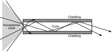
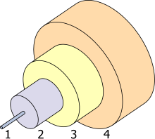
Optical fibers typically include a transparent core surrounded by a transparent cladding material with a lower index of refraction. Light is kept in the core by the phenomenon of total internal reflection which causes the fiber to act as a waveguide.[6] Fibers that support many propagation paths or transverse modes are called multi-mode fibers (MMF), while those that support a single mode are called single-mode fibers (SMF). Multi-mode fibers generally have a wider core diameter and are used for short-distance communication links and for applications where high power must be transmitted.[citation needed] Single-mode fibers are used for most communication links longer than 1,000 meters (3,300 ft).[citation needed]
An important aspect of a fiber optic communication is that of extension of the fiber optic cables such that the losses brought about by joining two different cables is kept to a minimum.[7] Joining lengths of optical fiber often proves to be more complex than joining electrical wire or cable and involves careful cleaving of the fibers, perfect alignment of the fiber cores, and the splicing of these aligned fiber cores. For applications that demand a permanent connection a mechanical splice which holds the ends of the fibers together mechanically could be used or a fusion splice that uses heat to fuse the ends of the fibers together could be used. Temporary or semi-permanent connections are made by means of specialized optical fiber connectors.
The field of applied science and engineering concerned with the design and application of optical fibers is known as fiber optics

Uses
Communication
Optical fiber can be used as a medium for telecommunication and computer networking because it is flexible and can be bundled as cables. It is especially advantageous for long-distance communications, because light propagates through the fiber with little attenuation compared to electrical cables. This allows long distances to be spanned with fewrepeaters.
The per-channel light signals propagating in the fiber have been modulated at rates as high as 111 gigabits per second (Gbit/s) by NTT,[29][30] although 10 or 40 Gbit/s is typical in deployed systems.[31][32] In June 2013, researchers demonstrated transmission of 400 Gbit/s over a single channel using 4-mode orbital angular momentum multiplexing.[33]
Each fiber can carry many independent channels, each using a different wavelength of light (wavelength-division multiplexing (WDM)). The net data rate (data rate without overhead bytes) per fiber is the per-channel data rate reduced by the FEC overhead, multiplied by the number of channels (usually up to eighty in commercial dense WDMsystems as of 2008). As of 2011 the record for bandwidth on a single core was 101 Tbit/s (370 channels at 273 Gbit/s each).[34] The record for a multi-core fiber as of January 2013 was 1.05 petabits per second. [35] In 2009, Bell Labs broke the 100 (petabit per second)×kilometer barrier (15.5 Tbit/s over a single 7,000 km fiber).[36]
For short distance application, such as a network in an office building, fiber-optic cabling can save space in cable ducts. This is because a single fiber can carry much more data than electrical cables such as standard category 5 Ethernet cabling, which typically runs at 100 Mbit/s or 1 Gbit/s speeds. Fiber is also immune to electrical interference; there is no cross-talk between signals in different cables, and no pickup of environmental noise. Non-armored fiber cables do not conduct electricity, which makes fiber a good solution for protecting communications equipment in high voltage environments, such as power generation facilities, or metal communication structures prone to lightning strikes. They can also be used in environments where explosive fumes are present, without danger of ignition. Wiretapping (in this case, fiber tapping) is more difficult compared to electrical connections, and there are concentric dual-core fibers that are said to be tap-proof.[37]
Fibers are often also used for short-distance connections between devices. For example, most high-definition televisions offer a digital audio optical connection. This allows the streaming of audio over light, using the TOSLINK protocol.
Advantages over copper wiring
The advantages of optical fiber communication with respect to copper wire systems are:
- Broad bandwidth
- A single optical fiber can carry over 3,000,000 full-duplex voice calls or 90,000 TV channels.
- Immunity to electromagnetic interference
- Light transmission through optical fibers is unaffected by other electromagnetic radiation nearby. The optical fiber is electrically non-conductive, so it does not act as an antenna to pick up electromagnetic signals. Information traveling inside the optical fiber is immune to electromagnetic interference, even electromagnetic pulses generated by nuclear devices.
- Low attenuation loss over long distances
- Attenuation loss can be as low as 0.2 dB/km in optical fiber cables, allowing transmission over long distances without the need for repeaters.
- Electrical insulator
- Optical fibers do not conduct electricity, preventing problems with ground loops and conduction of lightning. Optical fibers can be strung on poles alongside high voltage power cables.
- Material cost and theft prevention
- Conventional cable systems use large amounts of copper. In some places, this copper is a target for theft due to its value on the scrap market.
- Security of information passed down the cable
- Copper can be tapped with very little chance of detection.
Principle of operation
An optical fiber is a cylindrical dielectric waveguide (nonconducting waveguide) that transmits light along its axis, by the process of total internal reflection. The fiber consists of a core surrounded by a cladding layer, both of which are made of dielectric materials. To confine the optical signal in the core, the refractive index of the core must be greater than that of the cladding. The boundary between the core and cladding may either be abrupt, in step-index fiber, or gradual, in graded-index fiber.
Index of refraction
Main article: Refractive index
The index of refraction (or refractive index) is a way of measuring the speed of light in a material. Light travels fastest in a vacuum, such as in outer space. The speed of light in a vacuum is about 300,000 kilometers (186,000 miles) per second. The refractive index of a medium is calculated by dividing the speed of light in a vacuum by the speed of light in that medium. The refractive index of a vacuum is therefore 1, by definition. A typical singlemode fiber used for telecommunications has a cladding made of pure silica, with an index of 1.444 at 1,500 nm, and a core of doped silica with an index around 1.4475.[45]The larger the index of refraction, the slower light travels in that medium. From this information, a simple rule of thumb is that a signal using optical fiber for communication will travel at around 200,000 kilometers per second. To put it another way, the signal will take 5 milliseconds to travel 1,000 kilometers in fiber. Thus a phone call carried by fiber between Sydney and New York, a 16,000-kilometer distance, means that there is a minimum delay of 80 milliseconds (about  of a second) between when one caller speaks and the other hears. (The fiber in this case will probably travel a longer route, and there will be additional delays due to communication equipment switching and the process of encoding and decoding the voice onto the fiber).
 of a second) between when one caller speaks and the other hears. (The fiber in this case will probably travel a longer route, and there will be additional delays due to communication equipment switching and the process of encoding and decoding the voice onto the fiber).
Total internal reflection
Main article: Total internal reflection
When light traveling in an optically dense medium hits a boundary at a steep angle (larger than the critical angle for the boundary), the light is completely reflected. This is called total internal reflection. This effect is used in optical fibers to confine light in the core. Light travels through the fiber core, bouncing back and forth off the boundary between the core and cladding. Because the light must strike the boundary with an angle greater than the critical angle, only light that enters the fiber within a certain range of angles can travel down the fiber without leaking out. This range of angles is called the acceptance cone of the fiber. The size of this acceptance cone is a function of the refractive index difference between the fiber's core and cladding.
In simpler terms, there is a maximum angle from the fiber axis at which light may enter the fiber so that it will propagate, or travel, in the core of the fiber. The sine of this maximum angle is the numerical aperture (NA) of the fiber. Fiber with a larger NA requires less precision to splice and work with than fiber with a smaller NA. Single-mode fiber has a small NA.
Multi-mode fiber
Main article: Multi-mode optical fiber
Fiber with large core diameter (greater than 10 micrometers) may be analyzed by geometrical optics. Such fiber is called multi-mode fiber, from the electromagnetic analysis (see below). In a step-index multi-mode fiber, rays of light are guided along the fiber core by total internal reflection. Rays that meet the core-cladding boundary at a high angle (measured relative to a line normal to the boundary), greater than the critical angle for this boundary, are completely reflected. The critical angle (minimum angle for total internal reflection) is determined by the difference in index of refraction between the core and cladding materials. Rays that meet the boundary at a low angle are refracted from the core into the cladding, and do not convey light and hence information along the fiber. The critical angle determines the acceptance angle of the fiber, often reported as a numerical aperture. A high numerical aperture allows light to propagate down the fiber in rays both close to the axis and at various angles, allowing efficient coupling of light into the fiber. However, this high numerical aperture increases the amount of dispersion as rays at different angles have different path lengths and therefore take different times to traverse the fiber.
In graded-index fiber, the index of refraction in the core decreases continuously between the axis and the cladding. This causes light rays to bend smoothly as they approach the cladding, rather than reflecting abruptly from the core-cladding boundary. The resulting curved paths reduce multi-path dispersion because high angle rays pass more through the lower-index periphery of the core, rather than the high-index center. The index profile is chosen to minimize the difference in axial propagation speeds of the various rays in the fiber. This ideal index profile is very close to a parabolic relationship between the index and the distance from the axis.
Single-mode fiber
Fiber with a core diameter less than about ten times the wavelength of the propagating light cannot be modeled using geometric optics. Instead, it must be analyzed as an electromagnetic structure, by solution of Maxwell's equations as reduced to the electromagnetic wave equation. The electromagnetic analysis may also be required to understand behaviors such as speckle that occur when coherent light propagates in multi-mode fiber. As an optical waveguide, the fiber supports one or more confined transverse modes by which light can propagate along the fiber. Fiber supporting only one mode is called single-mode or mono-mode fiber. The behavior of larger-core multi-mode fiber can also be modeled using the wave equation, which shows that such fiber supports more than one mode of propagation (hence the name). The results of such modeling of multi-mode fiber approximately agree with the predictions of geometric optics, if the fiber core is large enough to support more than a few modes.
The waveguide analysis shows that the light energy in the fiber is not completely confined in the core. Instead, especially in single-mode fibers, a significant fraction of the energy in the bound mode travels in the cladding as an evanescent wave.
The most common type of single-mode fiber has a core diameter of 8–10 micrometers and is designed for use in the near infrared. The mode structure depends on the wavelength of the light used, so that this fiber actually supports a small number of additional modes at visible wavelengths. Multi-mode fiber, by comparison, is manufactured with core diameters as small as 50 micrometers and as large as hundreds of micrometers.


No comments:
Post a Comment