A rectifier is an electrical device that converts alternating current (AC), which periodically reverses direction, to direct current (DC), which flows in only one direction. The process is known as rectification. Physically, rectifiers take a number of forms, includingvacuum tube diodes, mercury-arc valves, copper and selenium oxide rectifiers, semiconductor diodes, silicon-controlled rectifiers and other silicon-based semiconductor switches. Historically, even synchronous electromechanical switches and motors have been used. Early radio receivers, called crystal radios, used a "cat's whisker" of fine wire pressing on a crystal of galena (lead sulfide) to serve as a point-contact rectifier or "crystal detector".
Rectifiers have many uses, but are often found serving as components of DC power supplies and high-voltage direct current power transmission systems. Rectification may serve in roles other than to generate direct current for use as a source of power. As noted,detectors of radio signals serve as rectifiers. In gas heating systems flame rectification is used to detect presence of a flame.
Because of the alternating nature of the input AC sine wave, the process of rectification alone produces a DC current that, though unidirectional, consists of pulses of current. Many applications of rectifiers, such as power supplies for radio, television and computer equipment, require a steady constant DC current (as would be produced by a battery). In these applications the output of the rectifier is smoothed by an electronic filter (usually a capacitor) to produce a steady current.More complex circuitry that performs the opposite function, converting DC to AC, is called an inverter
.
Rectifier devices
Before the development of silicon semiconductor rectifiers, vacuum tube thermionic diodes and copper oxide- or selenium-based metal rectifier stacks were used.[1] With the introduction of semiconductor electronics, vacuum tube rectifiers became obsolete, except for some enthusiasts of vacuum tube audio equipment. For power rectification from very low to very high current, semiconductor diodes of various types (junction diodes, Schottky diodes, etc.) are widely used.
Rectifier circuits[edit]
Rectifier circuits may be single-phase or multi-phase (three being the most common number of phases). Most low power rectifiers for domestic equipment are single-phase, but three-phase rectification is very important for industrial applications and for the transmission of energy as DC (HVDC).
Single-phase rectifiers
Half-wave rectification
In half wave rectification of a single-phase supply, either the positive or negative half of the AC wave is passed, while the other half is blocked. Because only one half of the input waveform reaches the output, mean voltage is lower. Half-wave rectification requires a single diode in a single-phase supply, or three in a three-phase supply. Rectifiers yield a unidirectional but pulsating direct current; half-wave rectifiers produce far more ripple than full-wave rectifiers, and much more filtering is needed to eliminate harmonics of the AC frequency from the output.
Full-wave rectification
A full-wave rectifier converts the whole of the input waveform to one of constant polarity (positive or negative) at its output. Full-wave rectification converts both polarities of the input waveform to pulsating DC (direct current), and yields a higher average output voltage. Two diodes and a center tapped transformer, or four diodes in a bridge configurationand any AC source (including a transformer without center tap), are needed.[3] Single semiconductor diodes, double diodes with common cathode or common anode, and four-diode bridges, are manufactured as single components.
Three-phase rectifiers
Thyristors are commonly used in place of diodes to create a circuit that can regulate the output voltage. Many devices that provide direct current actually generate three-phase AC. For example, an automobile alternator contains six diodes, which function as a full-wave rectifier for battery charging.Single-phase rectifiers are commonly used for power supplies for domestic equipment. However, for most industrial and high-power applications, three-phase rectifier circuits are the norm. As with single-phase rectifiers, three-phase rectifiers can take the form of a half-wave circuit, a full-wave circuit using a center-tapped transformer, or a full-wave bridge circuit.
Three-phase, half-wave circuit
An uncontrolled three-phase, half-wave circuit requires three diodes, one connected to each phase. This is the simplest type of three-phase rectifier but suffers from relatively high harmonic distortion on both the AC and DC connections. This type of rectifier is said to have a pulse-number of three, since the output voltage on the DC side contains three distinct pulses per cycle of the grid frequency.
Three-phase, full-wave circuit using center-tapped transformer
If the AC supply is fed via a transformer with a center tap, a rectifier circuit with improved harmonic performance can be obtained. This rectifier now requires six diodes, one connected to each end of each transformer secondary winding. This circuit has a pulse-number of six, and in effect, can be thought of as a six-phase, half-wave circuit.
Before solid state devices became available, the half-wave circuit, and the full-wave circuit using a center-tapped transformer, were very commonly used in industrial rectifiers using mercury-arc valves.[4] This was because the three or six AC supply inputs could be fed to a corresponding number of anode electrodes on a single tank, sharing a common cathode.
With the advent of diodes and thyristors, these circuits have become less popular and the three-phase bridge circuit has become the most common circuit.
Rectifier efficiency
Rectifier efficiency (η) is defined as the ratio of DC output power to the input power from the AC supply. Even with ideal rectifiers with no losses, the efficiency is less than 100% because some of the output power is AC power rather than DC which manifests as ripple superimposed on the DC waveform. For a half-wave rectifier efficiency is very poor,[6]
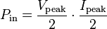
(the divisors are 2 rather than √2 because no power is delivered on the negative half-cycle)

Thus maximum efficiency for a half-wave rectifier is,

Similarly, for a full-wave rectifier,
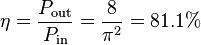
Efficiency is reduced by losses in transformer windings and power dissipation in the rectifier element itself. Efficiency can be improved with the use of smoothing circuits which reduce the ripple and hence reduce the AC content of the output. Three-phase rectifiers, especially three-phase full-wave rectifiers, have much greater efficiencies because the ripple is intrinsically smaller. In some three-phase and multi-phase applications the efficiency is high enough that smoothing circuitry is unnecessary.[7]
Rectifier losses
A real rectifier characteristically drops part of the input voltage (a voltage drop, for silicon devices, of typically 0.7 volts plus an equivalent resistance, in general non-linear)—and at high frequencies, distorts waveforms in other ways. Unlike an ideal rectifier, it dissipates some power.
An aspect of most rectification is a loss from the peak input voltage to the peak output voltage, caused by the built-in voltage drop across the diodes (around 0.7 V for ordinary silicon p–n junction diodes and 0.3 V for Schottky diodes). Half-wave rectification and full-wave rectification using a center-tapped secondary produces a peak voltage loss of one diode drop. Bridge rectification has a loss of two diode drops. This reduces output voltage, and limits the available output voltage if a very low alternating voltage must be rectified. As the diodes do not conduct below this voltage, the circuit only passes current through for a portion of each half-cycle, causing short segments of zero voltage (where instantaneous input voltage is below one or two diode drops) to appear between each "hump".
Peak loss is very important for low voltage rectifiers (for example, 12 V or less) but is insignificant in high-voltage applications such as HVDC.
No comments:
Post a Comment