A transformer is an electrical device that transfers electrical energy between two or more circuits through electromagnetic induction. Commonly, transformers are used to increase or decrease the voltages of alternating current in electric power applications.
A varying current in the transformer's primary winding creates a varying magnetic flux in the transformer core and a varying magnetic field impinging on the transformer's secondary winding. This varying magnetic field at the secondary winding induces a varying electromotive force (EMF) or voltage in the secondary winding. Making use of Faraday's Law in conjunction with high magnetic permeability core properties, transformers can thus be designed to efficiently change AC voltages from one voltage level to another within power networks.
Since the invention of the first constant potential transformer in 1885, transformers have become essential for the transmission, distribution, and utilization of alternating current electrical energy.[3] A wide range of transformer designs are encountered in electronic and electric power applications. Transformers range in size from RF transformers less than a cubic centimeter in volume to units interconnecting thepower grid weighing hundreds of tons.
Basic principles
Ideal transformer
Ideal transformer equations (eq.)
By Faraday's law of induction
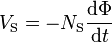 . . . (1)[a]
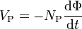 . . . (2)
Combining ratio of (1) & (2)
Turns ratio  . . . (3) where
. . . (3) where- for step-down transformers, a > 1
- for step-up transformers, a < 1
By law of Conservation of Energy, apparent,real and reactive power are each conserved in the input and output
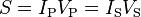 . . . (4)
 . (5)
. (5)
By Ohm's Law and ideal transformer identity
 . . . (6)
Apparent load impedance Z'L (ZL referred to the primary)
 . (7)
. (7)
For simplification or approximation purposes, it is very common to analyze the transformer as an ideal transformer model as presented in the two images. An ideal transformer is a theoretical, linear transformer that is lossless and perfectlycoupled; that is, there are no energy losses and flux is completely confined within the magnetic core. Perfect coupling implies infinitely high core magnetic permeability and winding inductances and zero net magnetomotive force.[5][c]
A varying current in the transformer's primary winding creates a varying magnetic flux in the core and a varying magnetic field impinging on the secondary winding. This varying magnetic field at the secondary induces a varying electromotive force (EMF) or voltage in the secondary winding. The primary and secondary windings are wrapped around a core of infinitely high magnetic permeability[d] so that all of the magnetic flux passes through both the primary and secondary windings. With a voltage sourceconnected to the primary winding and load impedance connected to the secondary winding, the transformer currents flow in the indicated directions. (See also Polarity.)
According to Faraday's law of induction, since the same magnetic flux passes through both the primary and secondary windings in an ideal transformer,[7] a voltage is induced in each winding, according to eq. (1) in the secondary winding case, according to eq. (2) in the primary winding case.[8] The primary EMF is sometimes termed counter EMF.[9][10][f] This is in accordance withLenz's law, which states that induction of EMF always opposes development of any such change in magnetic field.
The transformer winding voltage ratio is thus shown to be directly proportional to the winding turns ratio according to eq. (3).[11][12][g][h]
According to the law of Conservation of Energy, any load impedance connected to the ideal transformer's secondary winding results in conservation of apparent, real and reactive power consistent with eq. (4).
The ideal transformer identity shown in eq. (5) is a reasonable approximation for the typical commercial transformer, with voltage ratio and winding turns ratio both being inversely proportional to the corresponding current ratio.
By Ohm's Law and the ideal transformer identity:
- the secondary circuit load impedance can be expressed as eq. (6)
- the apparent load impedance referred to the primary circuit is derived in eq. (7) to be equal to the turns ratio squared times the secondary circuit load impedance
Classification parameters
Transformers can be classified in many ways, such as the following:- Power capacity: From a fraction of a volt-ampere (VA) to over a thousand MVA.
- Duty of a transformer: Continuous, short-time, intermittent, periodic, varying.
- Frequency range: Power-frequency, audio-frequency, or radio-frequency.
- Voltage class: From a few volts to hundreds of kilovolts.
- Cooling type: Dry and liquid-immersed – self-cooled, forced air-cooled; liquid-immersed – forced oil-cooled, water-cooled.
- Circuit application: Such as power supply, impedance matching, output voltage and current stabilizer or circuit isolation.
- Utilization: Pulse, power, distribution, rectifier, arc furnace, amplifier output, etc..
- Basic magnetic form: Core form, shell form.
- Constant-potential transformer descriptor: Step-up, step-down, isolation.
- General winding configuration: By EIC vector group – various possible two-winding combinations of the phase designations delta, wye or star, and zigzag or interconnected star;[p] other – autotransformer, Scott-T, zigzag grounding transformer winding.[84][85][86][87]
- Rectifier phase-shift winding configuration: 2-winding, 6-pulse; 3-winding, 12-pulse; . . . n-winding, [n-1]*6-pulse; polygon; etc..
Types
Various specific electrical application designs require a variety of transformer types. Although they all share the basic characteristic transformer principles, they are customize in construction or electrical properties for certain installation requirements or circuit conditions.- Autotransformer: Transformer in which part of the winding is common to both primary and secondary circuits.[88]
- Capacitor voltage transformer: Transformer in which capacitor divider is used to reduce high voltage before application to the primary winding.
- Distribution transformer, power transformer: International standards make a distinction in terms of distribution transformers being used to distribute energy from transmission lines and networks for local consumption and power transformers being used to transfer electric energy between the generator and distribution primary circuits.[88][89][q]
- Phase angle regulating transformer: A specialised transformer used to control the flow of real power on three-phase electricity transmission networks.
- Scott-T transformer: Transformer used for phase transformation from three-phase to two-phase and vice versa.[88]
- Polyphase transformer: Any transformer with more than one phase.
- Grounding transformer: Transformer used for grounding three-phase circuits to create a neutral in a three wire system, using a wye-delta transformer,[85][90] or more commonly, a zigzag grounding winding.[85][87][88]
- Leakage transformer: Transformer that has loosely coupled windings.
- Resonant transformer: Transformer that uses resonance to generate a high secondary voltage.
- Audio transformer: Transformer used in audio equipment.
- Output transformer: Transformer used to match the output of a valve amplifier to its load.
- Instrument transformer: Potential or current transformer used to accurately and safely represent voltage, current or phase position of high voltage or high power circuits.[88]
- Pulse transformer: Specialized small-signal transformer used to transmit digital signaling while providing electrical isolation, commonly used in Ethernet computer networks as 10BASE-T, 100BASE-T and 1000BASE-T.
No comments:
Post a Comment